This Article Contains Too Much Water
"We're starting development of a new game, and we need great-looking water. Can you do that?"
they asked me.
"Sure, no problem! Of course I can," I replied, though my voice betrayed me with a slight tremble.
"Oh, and it's on Unity, by the way?" At that moment it became clear that there was a lot of work ahead.
So, water. At that point I had never even seen Unity before, much less C#. I decided to build the prototype using tools I was already familiar with: C++ and Direct3D 9. What I actually knew how to do back then was fairly limited:
- scrolling normal maps to shape the surface,
- primitive displacement mapping based on them.
This time everything had to change. Realistic animated ocean surfaces. Much more sophisticated shading. Foam generation. A camera-dependent LOD system. I started digging through the Internet trying to figure out how all of this could be implemented.
The first step, naturally, was studying Jerry Tessendorf's famous paper:
Simulating Ocean Water by Jerry Tessendorf.
Academic papers packed with intimidating formulas were never my strongest side. After reading it a couple of times, I still understood very little. The overall idea was clear: every frame a height field is generated using a Fast Fourier Transform, and as a function of time it evolves smoothly to form a realistic ocean surface. But I didn't yet understand exactly what needed to be computed or how. Gradually I learned the intricacies of FFT processing on D3D9 shaders. A source-code package accompanying an article somewhere in the depths of the Internet helped immensely. Unfortunately, I spent over an hour trying to find it again while writing this article and failed. The first result eventually appeared. It was as beautiful as nuclear war:
The initial success was encouraging, and I began porting the water system to Unity while continuing to improve it. The naval-combat game imposed several requirements on the water system:
- Realistic visuals. Beautiful both up close and from a distance, with dynamic foam, scattering, and so on.
- Support for different weather conditions: calm seas, storms, and everything in between. Time-of-day changes as well.
- Ship buoyancy simulation on the generated ocean surface, including floating objects.
- Since the game is multiplayer, all players must see exactly the same water.
- Drawing on the water surface: artillery impact zones, foam generated by cannonball splashes, and similar effects.
Geometry
The chosen solution was a quadtree-like structure centered around the camera and rebuilt discretely as the observer moves. Why discretely? If the mesh moves continuously together with the camera, or if screen-space reprojection is used as described in Real-Time Water Rendering — Introducing the Projected Grid Concept, then distant waves begin to "jump" up and down because the geometric mesh lacks sufficient resolution when sampling the wave height field. The resulting flickering is very noticeable. To avoid it, one of three approaches is required:
- Dramatically increase the water mesh resolution.
- Flatten the geometry at long distances.
- Build and move the polygons in such a way that the shifts become invisible.
Our water was progressive (hehe), so I chose the third option. As with any similar technique (especially familiar to anyone who has worked on terrain rendering), it is necessary to eliminate T-junctions along LOD transitions. To solve this, three types of precomputed quads were generated at startup:
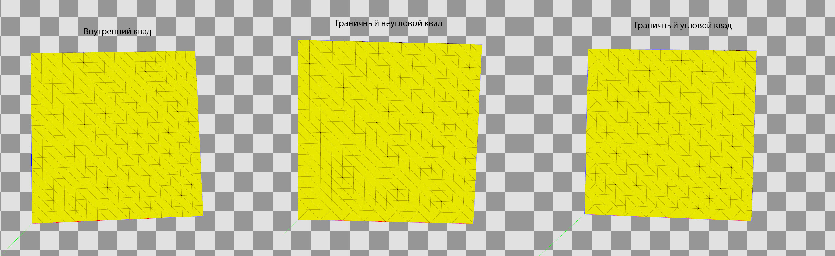
The first type is used for ordinary quads that are not transitioning to a lower level of detail. None of their edges have a reduced vertex count. The second type is used for boundary quads that are not corner pieces. The third type is used for corner transition quads. The final ocean mesh is built by rotating and scaling these three basic mesh types. This is how the renderer looks when different water LOD levels are visualized with different colors:
In the first few frames you can clearly see the connection between two different LOD levels. Here's a video showing how the frame becomes filled with water quads:
Keep in mind that all of this happened a long time ago (and is therefore completely untrue). Nowadays it can be implemented more efficiently and flexibly entirely on the GPU. For example: GPU Pro 5 — Quadtrees on the GPU. Rendering would require only a single draw call, and tessellation could further increase detail. Later the project migrated to D3D11, but I never got around to upgrading this part of the ocean renderer.
Wave Generation
This is where Fast Fourier Transform enters the picture. For a chosen wave-texture resolution (we'll call it that for now—later I'll explain what data it actually stores), initial data is generated using artist-controlled parameters:
- wind strength,
- wind direction,
- wave directional dependence,
- and others.
All of these values are fed into the formulas of the so-called Phillips spectrum. The generated data is then modified every frame according to time and processed through FFT. The result is a seamlessly tiling texture that contains vertex displacements for a flat mesh. Why not just store a heightmap? Because storing only vertical displacement produces an unrealistic boiling mass that merely resembles an ocean from a distance:
If displacements are computed for all three coordinates, beautiful sharp realistic waves emerge:
One animated texture isn't enough. Tiling becomes visible and close-up detail is insufficient. The solution was to generate not one FFT texture, but three:
- Large waves.
- Medium waves.
- Small waves.
The first layer defines the overall wave shape and is used for physics. The remaining layers add detail. Three FFT generators (the fourth view is the final combined result):
Each layer has its own independent parameters. The resulting textures are blended together inside the water shader to produce the final wave shape. Normal maps are generated alongside displacement maps for each layer. Water consistency between all players in a match is ensured by synchronizing ocean parameters when the battle starts. The server sends those parameters to every client.
Buoyancy Physics Model
Since the goal was not only to create beautiful visuals but also realistic ship behavior, and because the game needed to support stormy seas with large waves, another problem had to be solved: making objects float correctly on the generated ocean surface. My first attempt was to perform GPU readback of the wave texture. However, it quickly became clear that all naval-combat physics had to run on the server. That meant the ocean simulation—or at least the first layer that defines the primary wave shape—also had to be computed on the server. And servers generally don't have a fast and compatible GPU available. The solution was to write a complete CPU implementation of the GPU FFT generator as a native C++ plugin for Unity. I didn't implement the FFT algorithm itself. Instead, I used the implementation provided by Intel Performance Primitives (IPP). All surrounding systems and post-processing stages were written by me and later optimized using SSE and multithreading. This included:
- preparing FFT input data every frame,
- processing FFT output,
- generating the final wave offset map.
There was another interesting challenge caused by the buoyancy requirements. We needed a fast way to obtain wave height at any arbitrary world position. That sounds obvious, because it's the foundation of every buoyancy system. However, the FFT processor generates an offset map, not a height map. As a result, simply sampling the texture does not necessarily provide the wave height at the desired position. For simplicity, let's look at a 2D example:
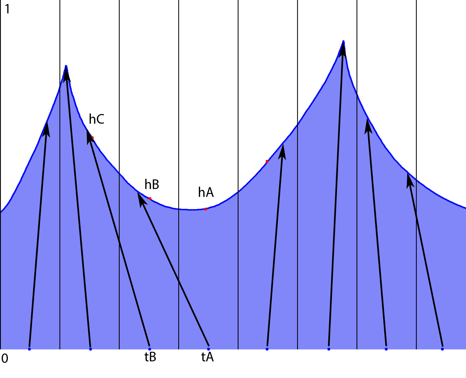
To generate waves, each texel (shown as vertical lines) stores a vector (the arrows) describing how a vertex of the flat mesh (blue points) moves toward its final position (arrow tip). Suppose we want to determine water height at position hB. If we sample texel tB, we obtain a displacement pointing somewhere near hC. That may differ significantly from the height we're actually interested in. There are two possible solutions. The first is: For every height query, scan neighboring texels until we find one whose displacement lands near the desired position. In our example, we'd eventually discover that texel tA contains the displacement that produces hB. Unfortunately, this is far from efficient. The required search radius depends on wave conditions. During a storm, displacement vectors can be very large.
The second solution is much better. After generating the offset map, convert it into a height map using a scattering approach. This means that every offset vector writes its resulting wave height into the position where it ends up. The generated data is stored in a separate array used for future height queries. In our example:
tA → hB
Therefore, cell tB will contain height hB. There is one complication. Cell tA may not receive any valid value because no displacement vector points into it. These empty cells are filled using neighboring values during a subsequent pass. This is what the displacement visualization looks like. Red indicates large displacement. Green indicates small displacement.
After that, everything becomes straightforward. Each ship defines a plane representing its approximate waterline. A rectangular grid of probe points is generated on that plane. These probes define where buoyancy forces are applied. For each probe:
- determine whether it lies below the water surface using the generated water height map,
- if it is underwater, apply an upward force to the ship's physics hull,
- scale the force according to the distance between the probe and the water surface,
- if the probe is above water, do nothing.
Gravity takes care of the rest. The real formulas are somewhat more complicated because they include tuning parameters for ship behavior, but that's the basic principle. In the buoyancy visualization below:
- blue cubes represent probe locations,
- downward lines represent the magnitude of the upward buoyancy force.
There was another interesting optimization on the server side. There is no reason to simulate different oceans for multiple battle instances if they all use identical weather conditions. In other words: identical FFT parameters should produce identical water. The logical solution was to create a pool of ocean simulators. Battle instances simply request water data from a simulator configured with the desired parameters. If several battles use the same settings, they all receive data from the same simulator. This was implemented using the Memory Mapped File API. When an FFT simulator is created, it exports handles to the memory blocks containing the generated data. Instead of launching a real simulator, a server instance launches a lightweight stub that simply reads data through those handles. There were a few amusing bugs related to this feature. Due to reference-counting mistakes, the simulator could be destroyed while the memory-mapped file itself remained alive because somebody still held an open handle. The data stopped updating because the simulator no longer existed. The ocean literally froze in place.
On the client side, wave-shape information is needed for:
- cannonball impacts,
- splash particle systems,
- foam generation.
Damage calculations occur on the server, which also needs to determine whether a cannonball hits the water. Large storm waves can completely hide ships. As a result, the server must perform proper height-map tracing in much the same way that ray marching is used in:
- parallax mapping,
- SSAO algorithms.
Shading
Pretty much the usual collection of effects. Reflections, refractions, subsurface scattering, Fresnel effects, specular highlights—all mixed together while taking water depth into account. Scattering is computed for wave crests depending on the sun position. Foam generation works as follows: First, foam patches are generated on wave crests. Wave height is used as the primary metric. These newly generated foam patches are then blended with foam from previous frames while simultaneously reducing their intensity. This creates elongated foam trails that follow moving wave crests.
The resulting foam texture is then used as a mask. Additional textures containing:
- bubbles,
- streaks,
- foam details,
are blended through that mask. The result is a fairly realistic and dynamic foam pattern on the water surface. A separate foam mask is generated for each FFT layer. (Remember, we have three of them.) All masks are blended together during the final shading pass. The video above visualizes the foam mask. The first and second FFT layers are shown. I'm modifying generator parameters, and the changes become visible directly in the generated texture. And here's a somewhat poorly tuned storm-ocean example. You can clearly see:
- wave shapes,
- generator capabilities,
- foam generation.
Drawing on the Water Surface
Example:
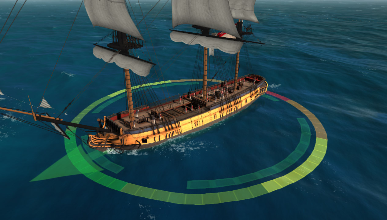
The system is used for:
- Visualizing cannonball spread areas.
- Drawing foam at cannonball impact locations.
- Ship wake trails.
- Displacing water beneath ships to prevent waves from flooding decks and cargo holds.
The obvious baseline solution is projective texturing. And that's exactly what was implemented. However, additional requirements appeared. Close-up views become blurry because of insufficient texture resolution. Increasing texture resolution helps, but only to a certain point. At the same time, projected markings must remain visible at long distances. Where is this exact same problem already solved? Correct: Shadow maps. And how is it solved there? Correct again: Cascaded Shadow Maps (also known as Parallel Split Shadow Maps). So I simply borrowed the idea and applied it to this problem. The camera frustum is divided into N sub-frustums. Typically:
N = 3–4
For each sub-frustum:
- Construct a bounding rectangle in the horizontal plane.
- Build an orthographic projection matrix covering that rectangle.
- Render all relevant objects using that orthographic camera.
Each camera renders into its own texture. Inside the ocean shader, all resulting textures are combined into a single seamless projected image.
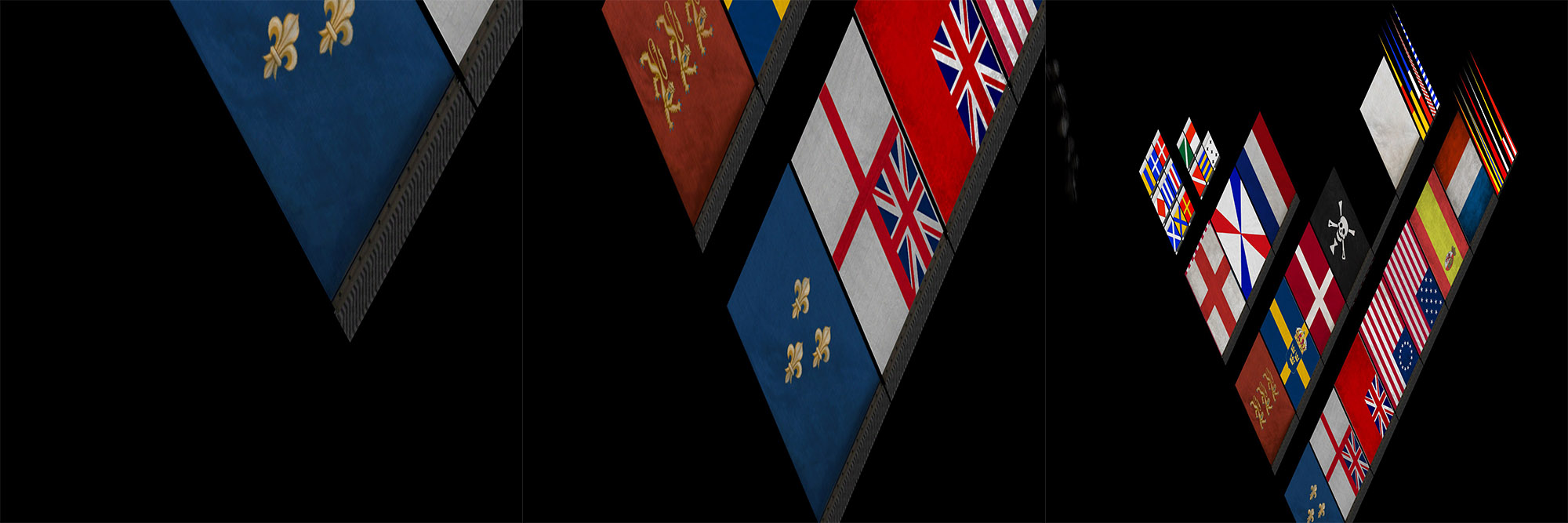
For demonstration purposes, I placed a giant plane with flag textures above the ocean:
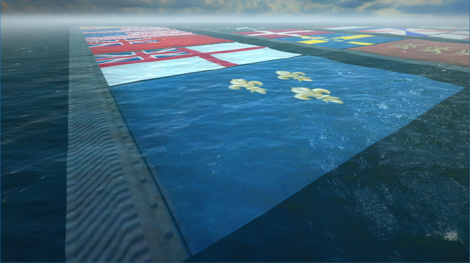
And here is what the individual splits contain:
In addition to ordinary projected images, the exact same mechanism is used to generate:
- foam masks (ship wakes and cannonball splashes),
- water-displacement masks beneath ships.
This initially required many cameras and many rendering passes. As you might expect, performance was terrible. After migrating to D3D11, the effect was greatly accelerated. Using a geometry shader, geometry could be replicated and rendered into different render targets using:
SV_RenderTargetArrayIndex
This allowed all splits to be generated much more efficiently.
Improvements and Modernization
D3D11 opens many doors. After migrating to both D3D11 and Unity 5, I rewrote the FFT generator using compute shaders. Visually, nothing changed. It just became a bit faster. Replacing reflection rendering from a dedicated camera pass with Screen Space Planar Reflections provided a noticeable performance boost. I already mentioned the optimization of Water Surface Objects above. As for moving the water mesh itself to a GPU quadtree implementation—well, I never got around to it. Many things could probably have been implemented in a simpler and more efficient way. For example, instead of maintaining a separate CPU simulator, I could have simply run the GPU version on the server using a WARP (software) D3D device. The data sizes involved weren't particularly large. Anyway, that's how it worked.
Back when development started, all of this was modern and exciting. Today some parts have become a little outdated. There are many more publicly available resources now. There's even a very similar open-source project on GitHub: Crest.
Most games that feature large oceans use broadly similar approaches nowadays.