Crysis
Crysis... How much is contained in that single word! :) It was difficult and incredibly fascinating. Every effect was a new discovery. It's one thing to read one or two paragraphs describing an implementation in the documentation, and quite another to explore and experiment with the effect yourself. At first, usually, nothing makes sense. Then, little by little, the technology starts to reveal itself, and the effect acquires a new kind of beauty. It usually ends with finding the most impressive manifestation of it and admiring it from every possible angle. :)
Yes, this is a reverse-engineering report on the Crysis renderer. Right from the start I'd like to make two remarks.
- There is documentation available describing various Crysis rendering technologies in a condensed form. I'm aware of three documents. The first is Martin Mittring's SIGGRAPH 2007 presentation (
p97-mittring.pdf). The second is Carsten Wenzel's GDC 2007 presentation (D3DTutorial_Crytek.pdf). And the last one is Tiago Sousa's article in GPU Gems 3. All of these sources helped me tremendously, so I highly recommend reading them. I won't spend much time discussing aspects that are already well described in those documents. - I have enormous respect for the development team. This is a world-class engineering team. Naturally, it's unlikely that I alone could completely understand every detail of the engine by simply diving into it. Therefore, it's entirely possible that during my analysis I missed something (perhaps even something important) or misunderstood certain parts.
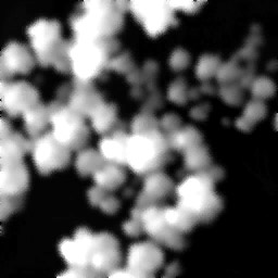
So, Crysis, Windows Vista, DX10. System configuration: Core2 Duo E6550, 3 GB RAM, GeForce 8600 GTS. All settings set to Ultra High. Probably everyone has heard about the famous Screen Space Ambient Occlusion (SSAO). Let's start there. The primary ingredient required to create this effect is camera-space normalized scene depth. Or, in plain English, a depth texture containing scene depth in camera space. The effect is rendered into a separate buffer, producing something like this:
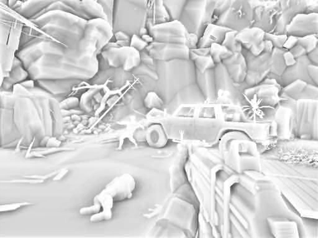
This is a fully real-time effect computed entirely on the GPU. How is it implemented? For every image pixel, eight vectors are used. You can imagine them as extending from the center of a cube toward its corners. Just like in the classic ambient occlusion algorithm, these vectors serve as rays used to test whether the current point is occluded by surrounding geometry. (In this case the tests are performed over a full sphere rather than a hemisphere because the surface normal is not available.) The next challenge is removing regular patterns from the sampling process. This is accomplished using a reflected-vector operation. Essentially the same as the reflect intrinsic in HLSL. The normal used for the reflection comes from the following texture: (enlarged 50 times)

The texture is only 4×4 texels. It is projected onto the screen such that every texel corresponds to one output pixel. This is achieved by tiling the texture screen_size / 4 times. As a result, every screen pixel receives a pseudo-random normal. All eight original vectors are then reflected around that pseudo-random normal, producing eight pseudo-random rays for testing. The rays have unit length. Their length is then scaled according to the distance of the processed point from the near plane. Pixels closer to the camera receive shorter rays. Distant pixels receive longer rays. Texture coordinates and depth values are offset along each ray, and a depth comparison is performed at the ray endpoint. If a ray penetrates geometry, the depth stored in the camera depth buffer will be smaller than the depth at the end of the ray. This increases the percentage of occluded rays, which ultimately reduces the amount of lighting received by the point. Unfortunately, the small number of test rays and the limited randomness of the sampling pattern result in a highly visible noisy structure:
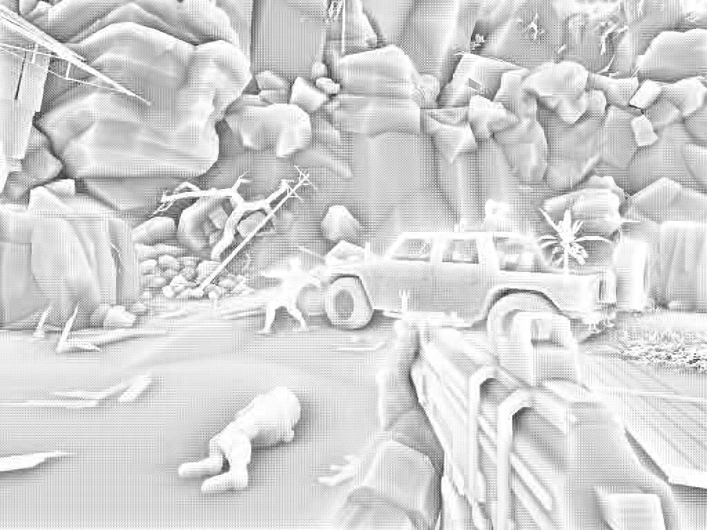
To compensate for this artifact, a fullscreen smoothing pass with color leak correction is applied. The scene depth texture is also used during this process. The resulting image is the one shown at the beginning of the section. For anyone interested in seeing this effect in action, here's a RenderMonkey project I created. It contains an almost complete reproduction of the Crysis SSAO implementation. Crysis.zip on upload.com.ua
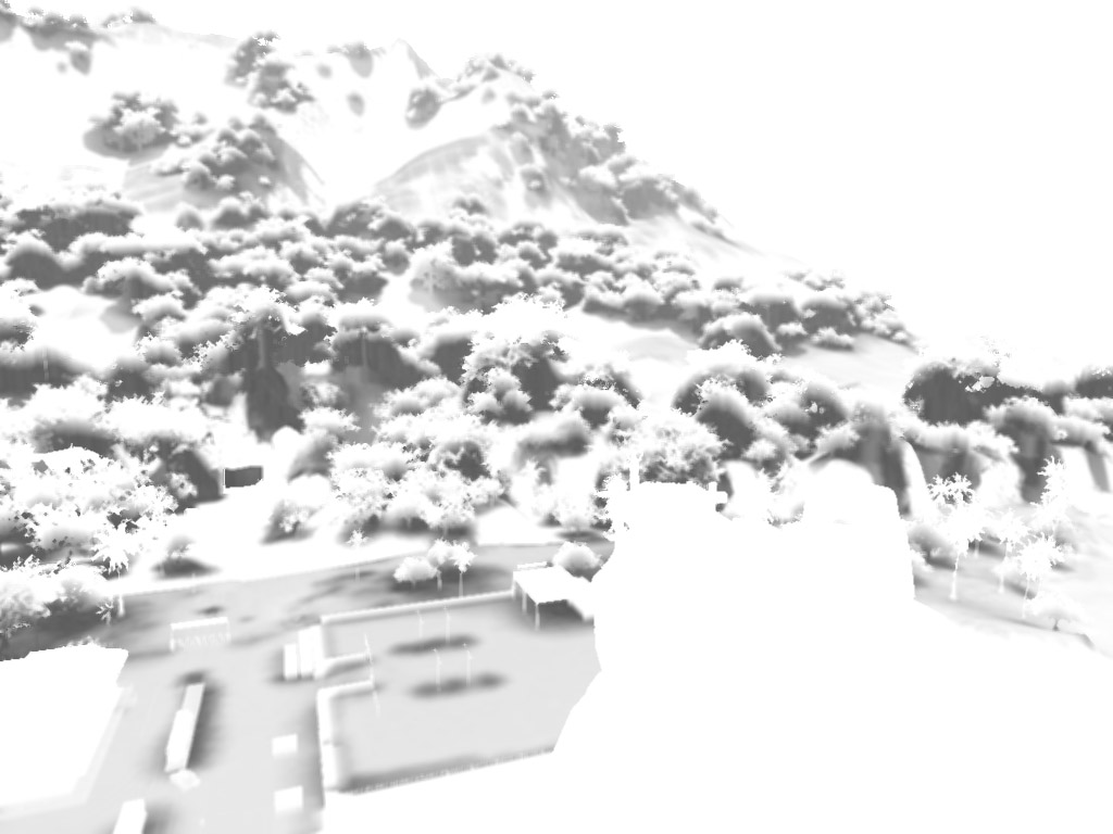
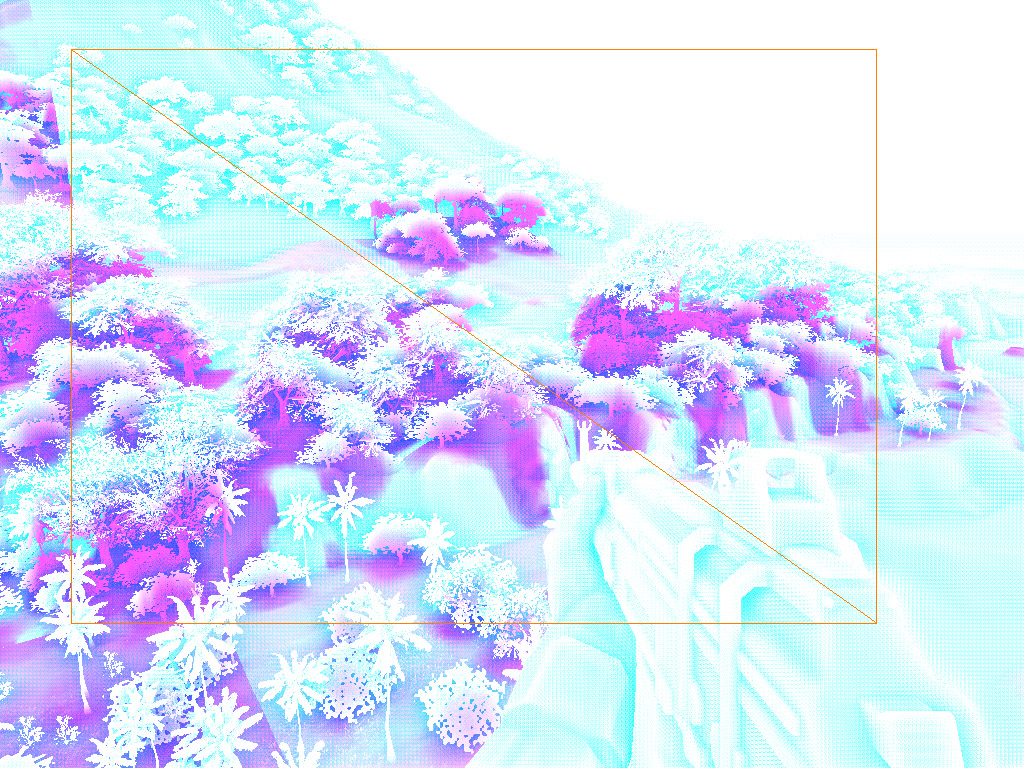
Next comes an effect that, as far as I remember, isn't described anywhere. Dynamic Terrain AO, or dynamic ambient occlusion for terrain. Rendering is performed into the G channel of the SSAO texture. (The SSAO itself is stored in the R channel.) This effect is intended to attenuate lighting on objects influenced by the terrain beneath them.
The way it is generated is quite clever. The terrain is divided into rectangular patches of varying size. Each patch has an associated rectangular box aligned to the lowest point of the patch. In other words, the lowest point of the terrain patch coincides with the bottom face of the box. Essentially it's an AABB, just stretched vertically. This box is rendered twice using the previously generated depth buffer. The rendering state is:
z-test on
z-write off
color write off
The first pass uses front-face culling. The second pass uses back-face culling. These two passes together form a stencil fill operation. In both cases:
StencilFunc = Always
ZFail = Replace
All other stencil operations are set to Keep. The only difference between the two passes is StencilRef. The front-face pass uses:
StencilRef = 6
(I have no idea why exactly 6. Just think of it as "some value greater than zero".) After rendering the box, the stencil buffer effectively highlights the screen region corresponding to the terrain patch. However, this information is not yet suitable for shading. Any object closer to the camera than the back face of the box will also become marked. To fix this, the box is rendered again using back-face culling and:
StencilRef = 0
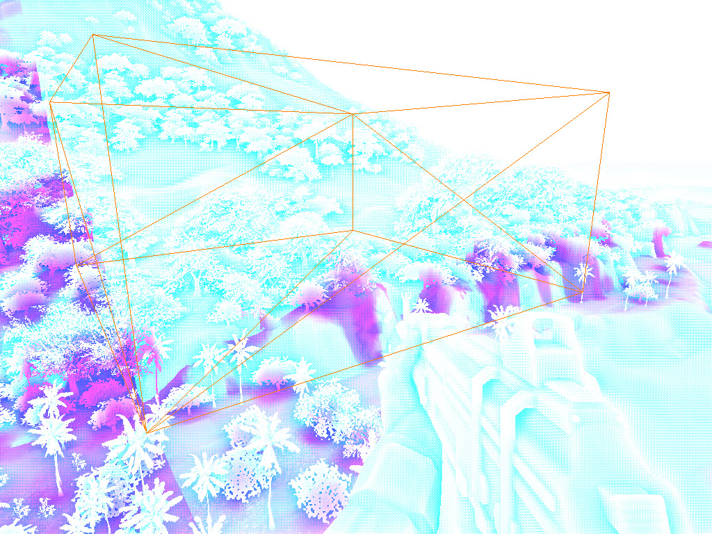
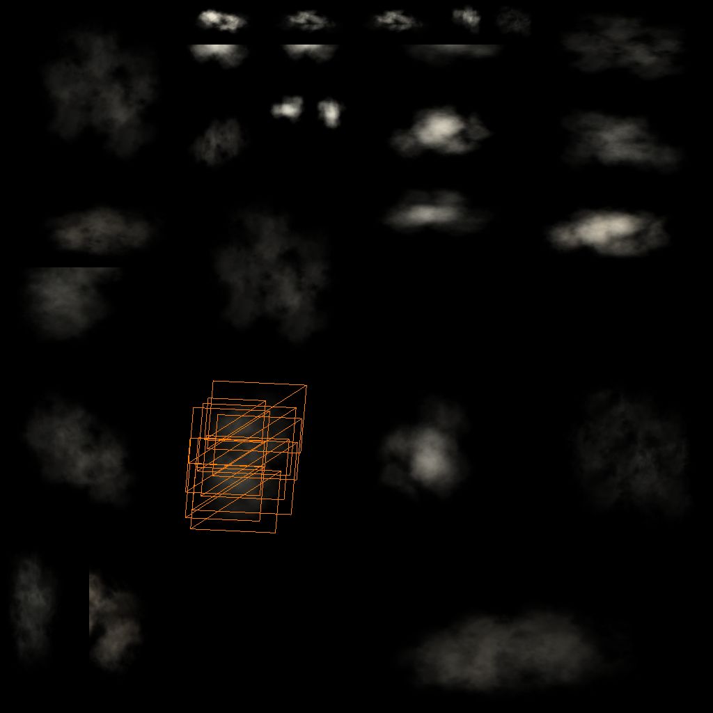
This removes stencil markings from pixels that are not actually inside the volume. For example, if the player is standing outside the terrain patch, the weapon held in front of the camera will not be included in the generated mask. To make this easier to understand, here's an illustration. The purple color represents Terrain AO stored in the G channel. Or more precisely, a reduction in brightness, since Terrain AO only produces shadowing.
Afterward, a screen-space rectangle corresponding to the previously mentioned terrain-patch AABB is rendered. The rendering state is configured as:
StencilFunc = Equal
StencilRef = 6
As a result, only pixels belonging to objects located inside the terrain patch volume are processed. For the image shown above, the bounding rectangle looks like this:
And now things get even more interesting. We're rendering entirely in screen space. How can anything useful possibly be done from there? Turns out, quite a lot. Each terrain patch has a pair of textures used during terrain rendering. Part of the information stored in them is reused when generating Terrain AO. Here they are:
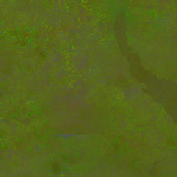
In Crytek terminology, they're named very creatively:
TerrainInfo0
TerrainInfo1
:)
From the first texture we need the precomputed coarse illumination from the sun. As far as I understand, this is something similar to static ambient occlusion. It resides in the R channel:
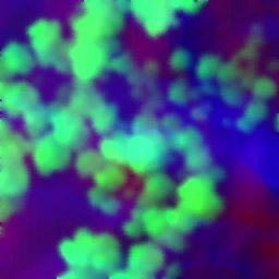
From the second texture we need the heightmap and vegetation height map. Those are stored in the A and G channels respectively.

So how do we use these textures? Naturally, we need texture coordinates that project them onto the terrain surface. The implementation is absolutely beautiful. The first step is reconstructing the world-space position of the pixel being processed. We already have the scene depth buffer. The formula is simple:
worldPosition =
    cameraWorldPosition +
    viewDirection * Z
One MAD instruction! How do we obtain the view direction vector? Simple. One option would be computing it per-vertex in the vertex shader for the corners of a screen-aligned quad. The interpolated values would then produce the desired directions. But the Crytek team went even further down the optimization path. The corresponding vector is supplied directly as per-vertex data through a separate vertex stream. Now that's optimization. :)
The next step is converting the world-space position into terrain-patch local coordinates. This is done by subtracting the coordinates of the AABB corner nearest to world-space origin from the pixel's world position. Converting the result into standard [0..1] UV coordinates is trivial. Simply divide by the patch width and length. Projective texture coordinates acquired. The rest is pure art. Knowing:
- the height of the current pixel,
- the terrain height beneath it,
- vegetation height,
- precomputed static AO, all of this information is combined using a collection of carefully tuned formulas and coefficients. The result is ambient shadowing beneath trees, darkening inside arches and caves, and similar effects. Distance-based fade-out is also implemented. The final result can be seen in the image shown at the beginning of this section.
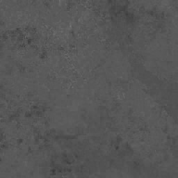
Water caustics. A beautiful effect. And fairly simple to implement. A projection matrix is constructed using the direction of the sunlight. This matrix is then used to generate texture coordinates for a normal map. Through various tricks involving a mix of high-frequency and low-frequency samples, a repetitive normal pattern is avoided. After all perturbations have been applied, the resulting normal is refracted relative to the sun direction using refract. The refraction angle is slightly different for each color channel (R, G, and B). This introduces a spectral shift into the final image. The resulting normals are then used to sample a texture like this:

The sampled value is raised to a power in order to sharpen the caustic pattern. The visibility of the caustics is determined by the dot product between the sun direction and the perturbed normal. Additional checks prevent caustics from appearing on surfaces facing away from the sun (angles greater than 90 degrees).
Clouds. They come in many varieties. For example, the highest clouds consist of a single polygon parallel to the ground. Their shading computes the influence of both the sun and the sky on the final color. Cloud density is calculated using texture-space tracing. The view vector toward the sun is transformed into cloud texture space. Eight samples are then taken from the density texture. The sampling step size is fixed. Lower clouds are shaded using atmospheric light scattering. A large cloud composed of many smaller cloud fragments is rendered into a separate texture. The resulting image is then projected back into the main scene.
Examples:

I believe the purpose of this approach was to create unique-looking cloud formations without imposing a significant computational burden. After all, the rendered cloud cluster can be reused across multiple frames. Since clouds change slowly, this approach works very well.
Ocean. The ocean surface is represented by a highly tessellated parallelepiped. The bottom plane lies at the water surface level. The upper plane lies at the player's eye level. Exactly as Martin Mittring described.
I still don't fully understand how they manipulate vertex coordinates so that the rasterized screen-space Z matches the water plane. Several hours of staring at shaders and scratching my head didn't help. :) Oh well. Waves are generated using vertex texture fetch. In the pixel shader everything is fairly standard:
- reflections
- refractions
- sun highlights
Chromatic aberration is also implemented for refraction. Different wavelengths of light are refracted at slightly different angles. This is achieved by applying small texture-coordinate offsets to each color channel individually. Exactly the same idea used earlier for caustics.
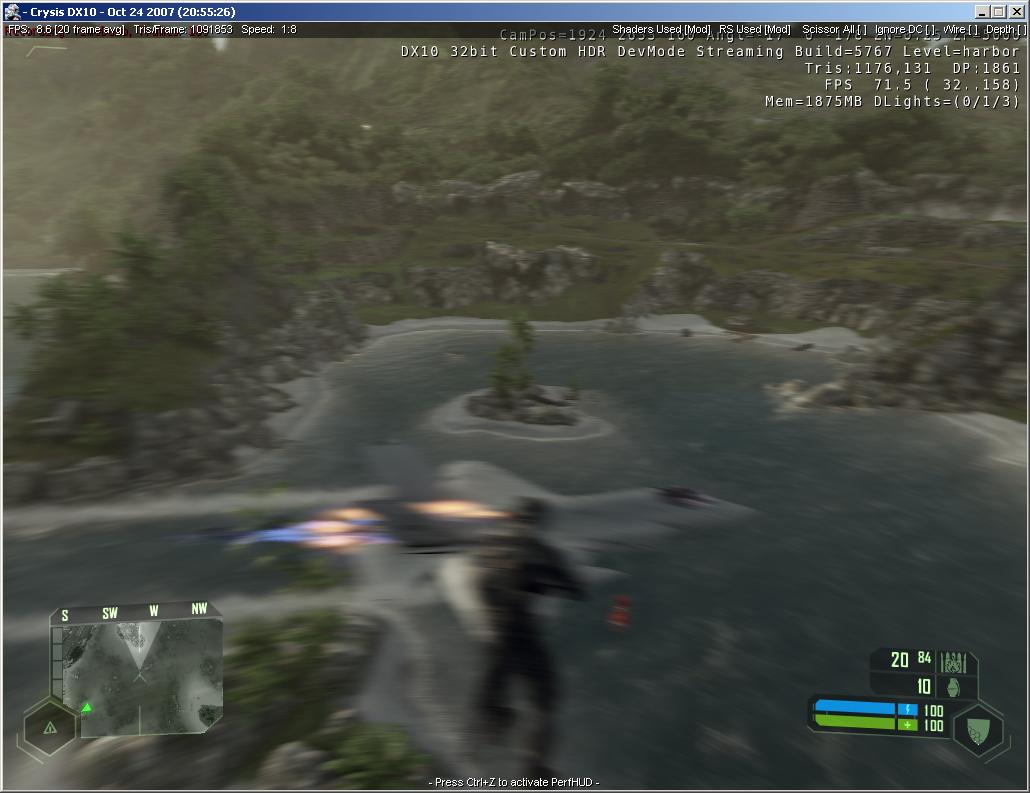
Now let's examine the rendering of a typical frame step by step. First come the reflection textures for water. Simplified shaders are used. Next, shadow maps are generated for all relevant light sources. I won't discuss shadows in detail because they're already described in the first document I mentioned at the beginning of this article. I'll simply say that everything written there is true. :) For directional lights:
- Cascaded Shadow Maps.
For point lights:
- cubemap-style shadows stored in a regular 2D texture. (Judging from the shaders, native cubemaps are also supported.)
For terrain:
- Variance Shadow Maps.
To achieve stronger blurring, a simple blur pass is used instead of Summed Area Tables. You've probably noticed by now that very few effects in Crysis can survive without the camera-space depth buffer. It is used almost everywhere. At this stage it is generated. The depth values are written into an R32F texture simultaneously with normal depth-buffer population. This helps reduce depth complexity to zero during subsequent passes. The next effect is SSAO combined with Terrain AO, both described above. After generation, the texture is blurred. Now it's time to generate the shadow mask used for so-called deferred shadowing. Shadows are rendered into a separate buffer to save instructions in the main rendering shaders. The main rendering pass targets an RGBA16F render target. HDR is everything. :) The depth buffer is configured for testing only. No depth writes occur. This is extremely important given the size of the shaders involved. An additional benefit is that objects no longer need to be sorted by distance. Several interesting techniques are also used during the main pass. For example, metallic materials use the Schlick and Cook-Torrance lighting models. (For the curious: there was a RenderMonkey demo and a short write-up. A detailed description can be found in Kelly Dempski and Emmanuel Viale's book Advanced Lighting and Materials with Shaders.) To reduce computational cost, parts of these functions are precomputed and stored in textures. All particle systems and clouds use the depth buffer to eliminate geometry-intersection artifacts. Vegetation batching is excellent. Nearby trees and bushes are rendered in small, highly detailed batches. Distant vegetation degenerates into screen-aligned quads rendered in enormous batches:
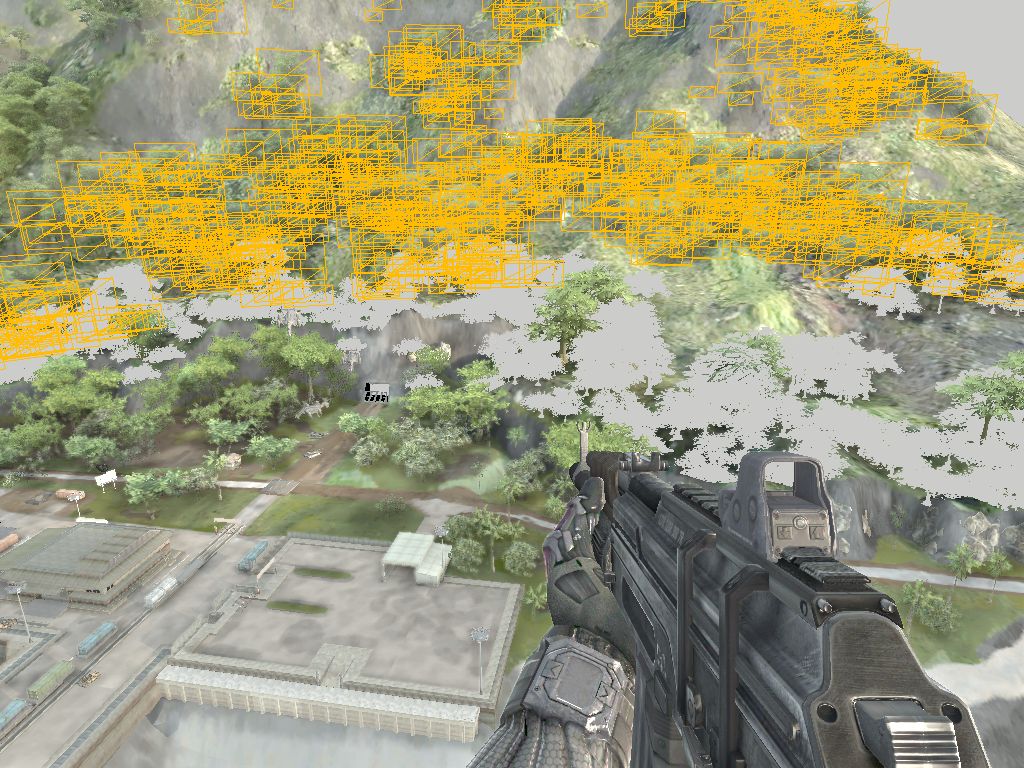
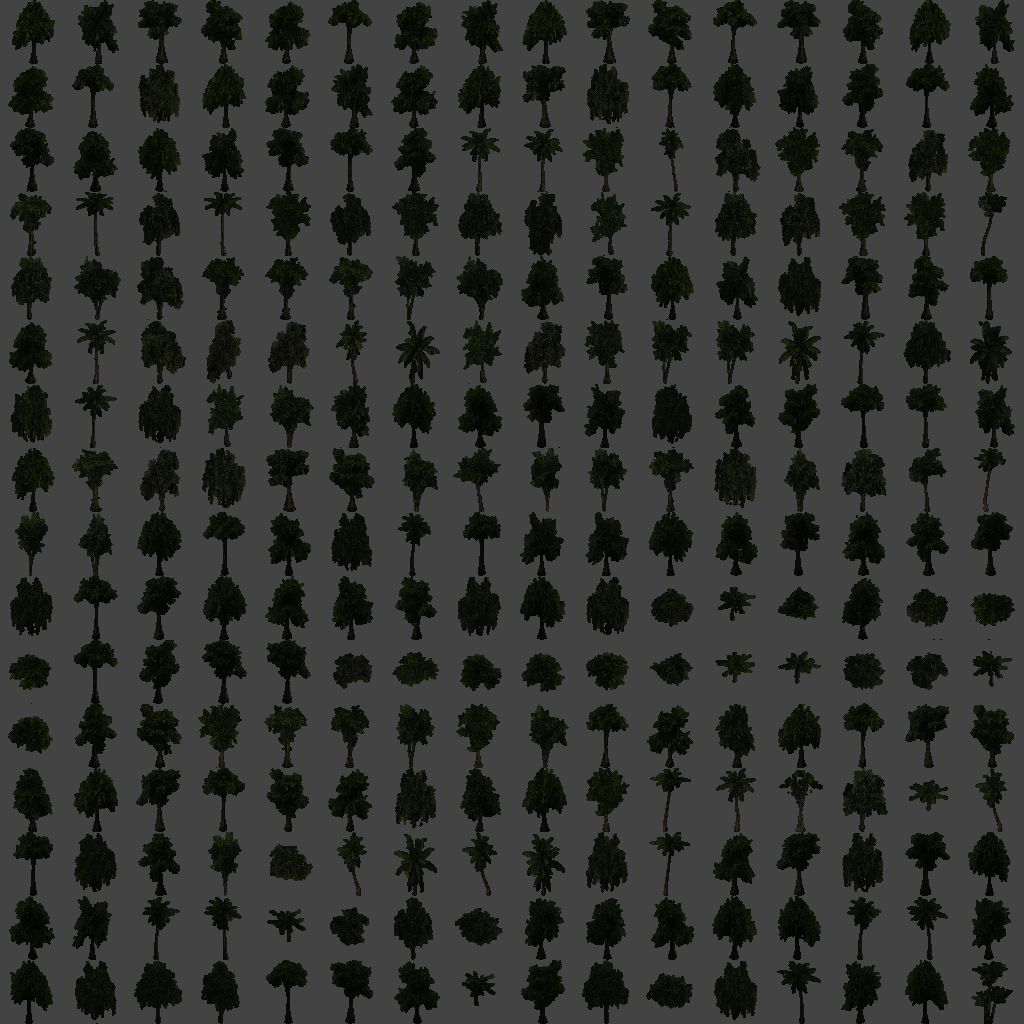
Vegetation rendering is described in a GPU Gems 3 article. I strongly recommend reading it. In short:
- animation is performed in the vertex shader,
- stiffness maps are used,
- foliage receives two-sided lighting,
- subsurface scattering is applied.
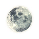
The sky uses completely physically based atmospheric light scattering. There is even this lovely moon texture:
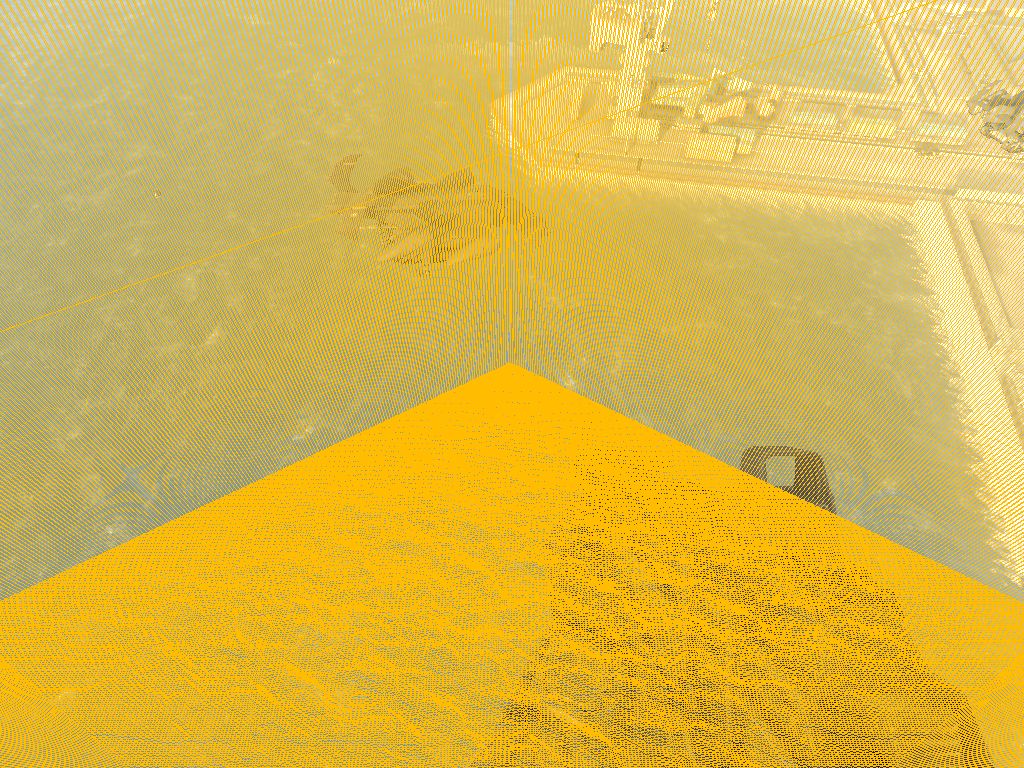
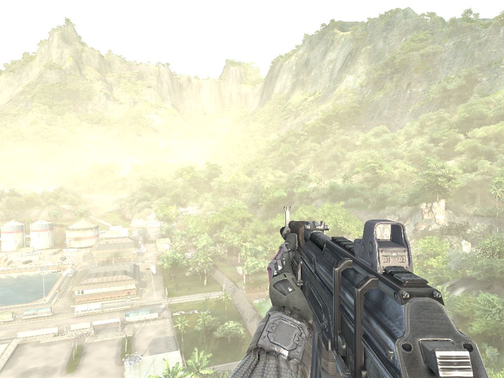
Terrain and certain scene elements are rendered in two passes. The first pass applies the base color. The second adds detail normals, caustics, and other enhancements. Finally, volumetric fog is rendered. And yes, it uses the camera-space depth texture once again. The result looks like this:
After the main pass, the bright regions are extracted from the scene texture. These are blurred to produce the bloom texture. The average scene luminance is then computed and stored in a 1×1 texture. Now it's time for all sorts of post-processing effects.
Motion blur. The image is blurred according to camera movement direction, taking pixel distance into account. (Yes, we're using the scene Z texture yet again.) Pixels closer to the camera receive stronger blur. Additional color-leak correction is applied to prevent weapon colors from bleeding into the scene.
Depth of Field. The scene image is downsampled and blurred. The result is then blended with the original image according to depth. And many other effects as well:
- chroma shift,
- radial blur when the player is stunned,
- wet-screen effects after emerging from water,
- and so on.
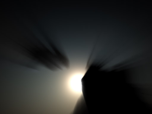
Next comes the tone-map resolve stage. In other words, conversion from HDR to LDR. But that's not all! :) There's another beautiful effect: light-shaft generation. The method is similar to the one described in the GPU Gems 3 article Volumetric Light Scattering as a Post-Process. In texture space, a ray is traced toward the sun. As we move along the ray, we determine whether the sun is occluded by geometry. This is done by comparing Z values against 1. (Remember: 0 corresponds to the near plane and 1 to the far plane.) The number of occluded samples determines the degree to which the sun is blocked. Distance attenuation is also applied.
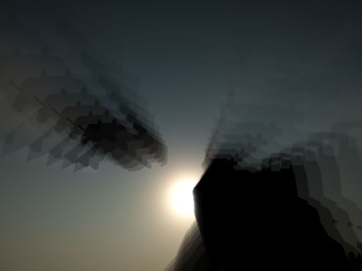
After three such passes using different sampling step sizes (to reduce discrete sampling artifacts), we obtain something like this:
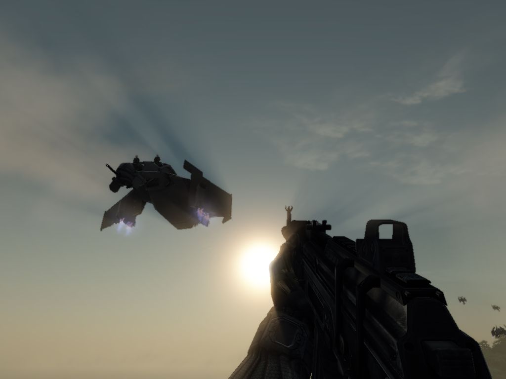
Final composition uses the so-called Soft Light Blend Mode, similar to Photoshop's implementation. This technique allows some regions of the image to become brighter while others become darker. You can read more about blending modes and their formulas here: http://www.pegtop.net/delphi/articles/blendmodes/softlight.htm Final image:
UI. Rendered element by element, letter by letter. Roughly 100 draw calls. Rendering complete.
Oh, right, there's snow too. :) I didn't spend much time investigating it. It's fairly advanced. The basic idea is to use the relationship between the world's up vector and the surface normal to determine where snow accumulates. Everything else is devoted to generating its irregular appearance and structure.
The frame contains around 2 million triangles. There wasn't much effort spent on aligning vertex formats. Draw-call counts can reach 2000. Almost all textures use DXT compression. Normals are stored in BC5 (ATI2N). That's about it. What stands out most is the pervasive use of the camera-space Z buffer. It's involved in almost every effect.
I'd like to thank the Crysis team for the wonderful experience, and Sergey "kss" for updating the mega-tool without which this fascinating adventure would never have happened. :)