PainKiller: Rendering Technologies
Some time ago I reverse-engineered PainKiller's renderer, but only very superficially. Since my mini-investigation of FlatOut's renderer unexpectedly received very positive feedback, I decided to take a serious look at this undoubtedly excellent game. So why PainKiller? The reasons are similar to those that motivated me to investigate FlatOut. Although the game is already somewhat old, I still really like the image it produces. Considering its excellent rendering performance, the renderer deserves every bit of praise.
So, the analysis was performed with maximum graphics settings enabled ("insane" in the configuration file) on a GeForce 6600.
The rendering of a frame consists of the following stages:
-
If a level contains water, a reflection map is rendered. I did not notice any simplifications in geometry or shaders compared to the main rendering pass (their detailed description follows later). Everything visible to the main camera is rendered. In other words, theoretically we could encounter sudden appearance/disappearance of reflections from objects that are outside the camera view. In practice, however, I tried to catch such a situation (not for very long, admittedly :) ). I failed.
-
Monster shadows. Each monster uses its own RTT (render target texture), A8R8G8B8, 128×128.
-
These textures are blurred twice using a simple 4-tap filter with texture coordinate offsets.
Result:

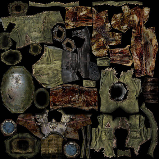
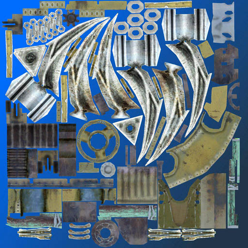
- Monsters. Hardware skinning is used. I don't know the exact number of bones, but considering that the renderer uses vs_1_1, I would guess around 20. The model naturally contains more bones than that, so it is split into several submeshes based on bone usage. The number of influences per vertex is 4. Skinned characters are rendered in a single pass, so lighting is applied immediately. Apparently only directional lights are supported, up to 5 of them. There is no pixel shader. Lighting calculated in the vertex shader is multiplied by the diffuse texture (which, by the way, is of very high quality).
Monster texture (original size 1024×1024):
Monster Shader
vs_1_1
dcl_position v0
dcl_normal v1
dcl_texcoord v2
dcl_blendweight v3
dcl_blendindices v4
dp4 oT0.x, v2, c24
dp4 oT0.y, v2, c25
dp4 oT1.x, v2, c24
dp4 oT1.y, v2, c25
dp3 r0.w, v3, c8.z
add r0.w, c8.z, -r0.w
mad r1, v4.zyxw, c8.y, c8.x
mov a0.x, r1.x
m3x3 r5.xyz, v1, c0[a0.x] // Skinning position using the first bone
m4x3 r6.xyz, v0, c0[a0.x] // Skinning normal
mul r3, r5.xyzz, v3.x // Blend according to bone weight
mul r4, r6.xyzz, v3.x
mov a0.x, r1.y
m3x3 r5.xyz, v1, c0[a0.x] // Here and below: same process for bones 2-4
m4x3 r6.xyz, v0, c0[a0.x]
mad r3, r5.xyzz, v3.y, r3
mad r4, r6.xyzz, v3.y, r4
mov a0.x, r1.z
m3x3 r5.xyz, v1, c0[a0.x]
m4x3 r6.xyz, v0, c0[a0.x]
mad r3, r5.xyzz, v3.z, r3
mad r4, r6.xyzz, v3.z, r4
mov r4.w, c8.z
m4x4 r0, r4, c0
mov oPos, r0
mad oFog, r0.z, c9.y, c9.x
mov r4, c11.xyzz
mov r0.w, c10.w
dp3 r0.x, r3, c13 // n dot l
dp3 r0.y, r3, c14 // n dot h
lit r1, r0 // Compute lighting from a directional light. Only one light is shown here, but there may be more. They are calculated the same way.
mad oD0, r1.y, c12, r4
mul r5, r1.z, c12
mul oD1, r5, c10
---
ps – ffp
- First pass for static geometry. FFP + simple shaders (1.1). When rendering terrain, two diffuse textures containing rock and grass patterns are used. They are blended using a predefined mask. A lightmap is also used.
Terrain Shader
vs_1_1
dcl_position v0
dcl_texcoord v1
dcl_texcoord1 v2
m4x4 r0, v0, c0
mov oPos, r0
mad oFog, r0.w, c9.y, c9.x
dp4 oT0.x, v1, c24
dp4 oT0.y, v1, c25
dp4 oT1.x, v1, c27
dp4 oT1.y, v1, c28
mov oT2.xy, v2.xyyy
mov oT3.xy, v2.xyyy

// approximately 12 instruction slots used

ps_1_1
tex t0 // ground texture 1
tex t1 // ground texture 2
tex t2 // blend map
tex t3 // light map
mul r0.xyz, t0, 1-t2 // Dark regions of the blend mask correspond to t0
+ mul r0.w, t0.w, 1-t2.w // Why parallelize the alpha and vector pipelines here? Not sure.
mad r0.xyz, t1, t2, r0 // Bright regions correspond to t1. Add the result.
+ mad r0.w, t1.w, t2.w, r0.w // Again...
mul_x2 r0.xyz, r0, t3 // Multiply by the lightmap and then by 2
+ mul r0.w, r0.w, t3.w // Alpha is not multiplied by 2.

// approximately 7 instruction slots used (4 texture, 3 arithmetic)
Example terrain blend mask:
Example terrain lightmap:

When rendering all other objects, a lightmap and a single diffuse texture are used. Nearby geometry also uses a detail texture.
Object Shader
vs_1_1
dcl_position v0
dcl_texcoord v1
dcl_texcoord1 v2
m4x4 r0, v0, c0
mov oPos, r0
mad oFog, r0.z, c9.y, c9.x // calculate fog
dp4 oT0.x, v1, c24 // some sort of rescaling. Present in all shaders. Didn't investigate it deeply.
dp4 oT0.y, v1, c25
dp4 oT1.x, v1, c27
dp4 oT1.y, v1, c28
mov oT2, v2

// approximately 11 instruction slots used
At the time of testing, the constants contained the following values:
// c24 – 20, 0, 0, 0
// c25 – 0, 20, 0, 0
// c27 – 20, 0, 0, 0
// c28 – 0, 20, 0, 0

ps – FFP
t0 – base
t1 – detail – not used for distant objects.
t2 – lightmap

texture blending formula:
(base + detail – 0.5) * lightmap * 2
Object lightmap (original size 1024×1024):
-
Water. First pass. Complex shaders. I didn't fully figure them out :) I won't include them here. A large number of input parameters are used. Vertex shader: 56 instructions Pixel shader: 31 instructions This pass applies reflections, animating them using two DuDv maps. Wave motion is created by animating vertices in the vertex shader. In fact, I only discovered that the water used per-vertex animation after analyzing the shader and noticing that vertex positions were being modified. Before that, I thought the water surface was completely flat.
-
Second pass for water. The water is lit by four directional light sources using per-vertex lighting.
Second Water Pass Shader
vs_1_1
dcl_position v0
dcl_normal v1
dcl_texcoord v2
m4x4 r0, v0, c0
mov oPos, r0
mad oFog, r0.z, c9.y, c9.x
dp4 oT0.x, v2, c24
dp4 oT0.y, v2, c25
dp4 oT1.x, v2, c27
dp4 oT1.y, v2, c28
mov r4, c11.xyzz // r4.xyzw = 0.125
mov r0.w, c10.w
m3x3 r3.xyz, v1, c4 // transform into view space
dp3 r0.x, r3, c13 // n dot l
dp3 r0.y, r3, c14 // n dot h
lit r1, r0 // lighting calculation. After this operation r1.y = diffuse, r1.z = specular
mad r4, r1.y, c12, r4 // c12 contains light color
mul r5, r1.z, c12 // same for specular
dp3 r0.x, r3, c16 // accumulate diffuse and specular contributions from three additional lights
dp3 r0.y, r3, c17
lit r1, r0
mad r4, r1.y, c15, r4
mad r5, r1.z, c15, r5
dp3 r0.x, r3, c19
dp3 r0.y, r3, c20
lit r1, r0
mad r4, r1.y, c18, r4
mad r5, r1.z, c18, r5
dp3 r0.x, r3, c22
dp3 r0.y, r3, c23
lit r1, r0
mad oD0, r1.y, c21, r4
mad r5, r1.z, c21, r5
mul oD1, r5, c10

// approximately 36 instruction slots used

ps – ffp
PainKiller contains another type of water as well. Instead of true reflections, it uses lightmaps. This type is used on levels containing large amounts of water. For example, the level C5L1_City_On_Water. The first type is used on the first level of the Battle Out Of Hell expansion: C6L1_Orphanage. I suspect the powerful editor allows water parameters to be varied extensively in order to achieve the desired visual style.
- Sky. Up to four layers are supported. Components of a three-layer sky: hemisphere, inner dome at the zenith, another hemisphere.
These layers are blended using standard alpha blending (
srcalpha,invsrcalpha) and use exactly the same shaders as terrain rendering. Unused layers (remember that terrain rendering uses two textures for blending) are replaced with a dummy texture.
Example sky textures:
Original size 2048×512
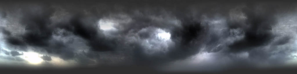
Original size 1024×1024
Original size 1024×1024
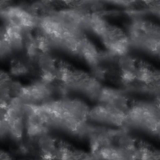
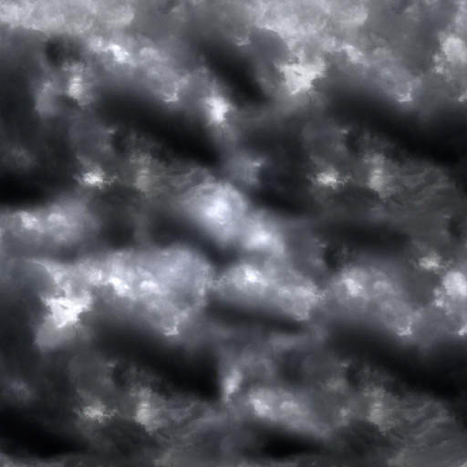
- Second pass for the scene – lighting. At this stage, both terrain and all other static objects are rendered in exactly the same way. Lighting is performed using a single point light source, calculated per pixel. The entire process is quite clever. To account for distance attenuation, the renderer uses an attenuation texture like this:

In the vertex shader, the distance from the light source to a vertex is calculated. By dividing the resulting distance by the light's influence radius, the vector is packed so that all distances affected by the light fall into the range [-1, 1]. The range is then remapped into [0, 1]. The resulting values are used as texture coordinates for sampling the attenuation texture. Since the texture address mode is set to Clamp, any lookups outside the texture simply sample its border. In our example, a simple circle texture is used, resulting in smooth attenuation with distance. However, if we used the same circle but inverted its colors, distant objects would become illuminated while nearby ones would remain dark. In short, this technique allows a huge variety of attenuation profiles.
Shaders used for static lighting:
Static Lighting Shader
vs_1_1
dcl_position v0
dcl_texcoord v1
dcl_normal v3
m4x4 r0, v0, c0
mov oPos, r0
mad oFog, r0.w, c9.y, c9.x
add r0, v0, -c13 // world position – light position
mul r1, r0, c12.w // c12.w contains the light range coefficient. After multiplication, all distances affected by the light fall into the range [-1, 1]
mad r1, r1, c8.w, c8.w // Pack vector from [-1, 1] into [0, 1]
mov oT0.xy, r1.xyyy // store xy into tc0
mov oT1.x, r1.z // store z into tc1
mov oT1.y, c8.w // c8.w = 0.5, giving us a 1D lookup along the center line of the texture
mov oT2, -r0 // vertex-to-light vector
dp4 oT3.x, v1, c33 // since c33 = 1000 and c34 = 0100, these two lines are a very clever way of writing mov oT3.xy, v1. Perhaps intended for future texture coordinate animation.
dp4 oT3.y, v1, c34
mov oD0, c12
mad oD1, v3, c8.w, c8.w // pack normal into color

// approximately 17 instruction slots used

ps_1_1
tex t0 // Circle texture, opaque outside, transparent inside. Otherwise white.
tex t1 // Same circle texture
tex t2 // normalized vertex-to-light vector from normalization cubemap
tex t3 // diffuse texture
mul r0.xyz, t3.w, v0 // diffuse color * base texture alpha
dp3_sat r1, v1_bx2, t2_bx2 // n dot l
mul r0.xyz, r0, r1
+ add r0.w, 1-t0.w, -t1.w // Distance attenuation using the circle texture. t0.w attenuates xy, t1.w attenuates z.
mul r0.xyz, r0, r0.w // Apply computed attenuation to lighting.
+ mul r0.w, r1.w, r0.w
mul_x2 r0.xyz, r0, t3 // Multiply by diffuse texture

// approximately 9 instruction slots used (4 texture, 5 arithmetic)
The main render states are:
Depth Write = false
SrcBlend = one
DstBlend = one
In other words, lighting accumulation uses:
pixel color + incoming color
-
Third pass for static geometry (only if shadows are enabled). Geometry is rendered once again, this time projecting shadow textures from monsters onto the environment. Nothing particularly interesting happens here, except that the shadows are blurred even more (two texture lookups per shadow texture).
-
Particles. Dynamic vertex and index buffers are used. FFP.
-
Weapons. Shader Model 3.0. Normal mapping from multiple (I observed two) directional light sources. Everything is fairly standard, except for one thing: the normal maps are stored in model space rather than tangent space. Instead, the light sources are transformed into model space as well. Weapon animations use hardware skinning (each vertex is influenced by two bones).
Weapon normal map (original size 1024×1024):
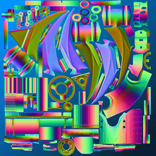
The specular mask is stored in the alpha channel of the normal map (original size 1024×1024):
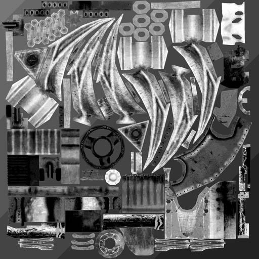
Diffuse texture (original size 1024×1024):
Weapon Shader
// Registers:
//
// Name Reg Size
// ------------ ----- ----
// GClipMat c0 4
// GFogParams c9 1
// GLightDir0 c13 1
// GHalfDir0 c14 1
// GLightDir1 c16 1
// GHalfDir1 c17 1
// GSkinBones c27 69

vs_3_0
def c4, 765.005859, 1, 0, 0
dcl_position v0
dcl_texcoord v1
dcl_blendweight v2
dcl_blendindices v3
dcl_position o0
dcl_fog o1.x
dcl_texcoord o2.xy
dcl_texcoord1 o3.xy
dcl_texcoord2 o4.xyz
dcl_texcoord3 o5.xyz
dcl_texcoord4 o6.xyz
dcl_texcoord5 o7.xyz
mul r0.xy, c4.x, v3.zyzw
mova a0.xy, r0
dp4 r1.x, v0, c27[a0.x] // Skinning
dp4 r1.y, v0, c28[a0.x]
dp4 r1.z, v0, c29[a0.x]
dp4 r2.x, v0, c27[a0.y]
dp4 r2.y, v0, c28[a0.y]
dp4 r2.z, v0, c29[a0.y]
lrp r0.xyz, v2.x, r1, r2 // Two bones, blend according to weights
mov r0.w, c4.y
dp4 o0.x, r0, c0 // x * wvp
dp4 o0.y, r0, c1 // y * wvp
mov r4.xyz, c28[a0.x] // Slightly tricky here. Since a model-space normal map is used instead of tangent-space, the light parameters (dir, half) are transformed into model space before being uploaded as constants. We then rotate the vectors according to the bone matrices.
mul r3.xyz, r4, c13.y // y component in animated model space
mul r1.xyz, r4, c14.y
mov r2.xyz, c27[a0.x]
mad r5.xyz, r2, c13.x, r3 // x component
mad r3.xyz, r2, c14.x, r1
mov r1.xyz, c29[a0.x]
mad o4.xyz, r1, c13.z, r5 // o4 - light vector 0 in animated model space
mad o5.xyz, r1, c14.z, r3 // o5 - half vector 0 in animated model space
mul r3.xyz, r4, c16.y
mul r4.xyz, r4, c17.y
mad r3.xyz, r2, c16.x, r3
mad r2.xyz, r2, c17.x, r4
mad o6.xyz, r1, c16.z, r3 // o6 - light vector 1 in animated model space
mad o7.xyz, r1, c17.z, r2 // o7 - half vector 1 in animated model space
dp4 r1.z, r0, c2 // z * wvp
dp4 r1.w, r0, c3 // w * wvp
mad o1.x, r1.z, c9.y, c9.x // fog
mov o0.zw, r1
mov o2.xy, v1 // tc0 pass-through
mov o3.xy, v1

// approximately 33 instruction slots used


// Name Reg Size
// ------------- ----- ----
// GLightEnable0 b0 1
// GLightEnable1 b1 1
// GAmbientColor c0 1
// GLightColor0 c1 1
// GLightColor1 c2 1
// ColorSampler s0 1
// NormalSampler s1 1

ps_3_0
def c3, 2, -1, 10, 0
dcl_texcoord v2.xy
dcl_texcoord1 v3.xy
dcl_texcoord2 v4.xyz
dcl_texcoord3 v5.xyz
dcl_texcoord4 v6.xyz
dcl_texcoord5 v7.xyz
dcl_2d s0
dcl_2d s1
texld_pp r0, v2, s0
texld r1, v3, s1
if b0
mad_pp r3.xyz, c3.x, r1, c3.y // unpack normal from normal map
nrm_pp r2.xyz, v4 // normalize light vector 0
nrm_pp r1.xyz, v5 // normalize half vector 0
dp3_sat_pp r2.w, r3, r2 // n dot l
dp3_sat_pp r2.z, r3, r1 // n dot h
pow_pp r1.z, r2.z, c3.z // calculate specular
mul_pp r2.xyz, r2.w, c1 // apply light color
mul_pp r1.xyz, r1.z, r2 // apply specular contribution
if b1 // same thing for the second light
nrm_pp r4.xyz, v7
nrm_pp r2.xyz, v6
dp3_sat_pp r4.w, r3, r4
dp3_sat_pp r2.z, r3, r2
pow_pp r3.w, r4.w, c3.z
mul_pp r2.xyz, r2.z, c2
mad_pp r1.xyz, r3.w, r2, r1
mad_pp r2.xyz, r2.w, c1, r2
endif
add r2.xyz, r2, c0 // add ambient light
mul r0.xyz, r0, r2 // apply diffuse texture
mad_pp oC0.xyz, r1.w, r1, r0 // alpha channel of normal map contains the specular mask
mov_pp oC0.w, r0.w
else
mul_pp oC0.xyz, r0, c0
mov_pp oC0.w, r0.w
endif

// approximately 45 instruction slots used (2 texture, 43 arithmetic)
-
Downsample the image, applying a small color remap to isolate bright areas.
-
Separable Gaussian blur. Horizontal and vertical, 13×13. The result is a bloom texture. Bloom texture:

- Blending with the bloom texture. FFP. The blend equation is:
blurred texture + scene texture
The resulting image looks particularly good with the dynamic sky.
- UI. There is almost no in-game UI in PainKiller. I suspect that's exactly why it was implemented so poorly :) Everything is rendered element by element, with no batching whatsoever. The developers put considerably more effort into the startup menu, however. The key configuration screen was especially amusing.
A few screenshots from NVPerfHUD:
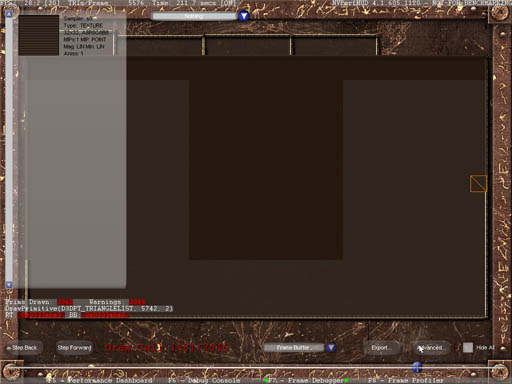
Redrawing almost the entire screen three times using such tiny rectangles takes a special kind of talent :) 2000 draw calls.
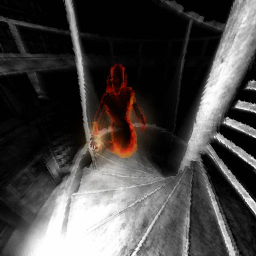
- Demon Mode. For those who haven't played the game, this is the mode that activates after collecting 66 souls, turning you into an immortal homicidal maniac. :) The rendering process is as follows: First, the scene is rendered normally into an RTT. Then a grayscale image is generated from it (using the standard approach:
dp3(pixel, float3(0.3, 0.59, 0.11))). After that, monsters are rendered using a special shader that utilizes normals and a gradient texture to highlight object silhouettes in red. Finally, a DuDv bump map is used to introduce image distortion. To produce a motion blur effect, the previous and current frames are blended together using weighted coefficients.
Demon Mode Shader
ps_1_1
tex t0 // Sample from the original texture
texbem t1, t0 // The membrane-like effect that appears when shooting in Demon Mode is implemented by tweaking the bumpenvmat texture stage state.
tex t2 // Use the previous frame texture to achieve a floating effect.
mul r0, t1, c0
mad r0, t2, c1, r0 // Blend current and previous frames using weights. Produces a motion-blur-like effect.
Gradient texture:
![]()
The resulting image looks like this:
And that's pretty much it.
Now for some general observations about the renderer.
-
Draw call count is low. Outdoor scenes usually stay below 1000 (occasionally exceeding it, but rarely). Indoor scenes are typically lower, sometimes significantly lower. Considering the number of rendering passes involved, this is a very good result.
-
Material and texture sorting is good. D3DXEffect is not used.
-
The art is simply outstanding. Effects are used where they are needed. Everything is carefully tuned and balanced. Level design is excellent. The textures are made with great attention to quality. Take a look around
C6L2_LoonyParkin the editor, for example. It's gorgeous. -
Video memory usage is between 100 and 120 MB (on a graphics card with 128 MB of VRAM). AGP memory usage is only 6 MB. You can definitely feel the touch of a skilled optimization engineer.
-
There are no geometry LODs. Glow particles are culled based on distance, however.
My conclusions (most of them overlap with those from the FlatOut 2 investigation):
-
The first thing to think about when designing a renderer is minimizing draw calls. PainKiller clearly demonstrates that a low draw call count leaves much more room for interesting and diverse rendering algorithms, even if they require multiple rendering passes. If a single pass already requires more than 1000 draw calls, then multi-pass techniques are most likely off the table.
-
Don't be afraid of precomputed lighting. Lightmaps not suitable for your project? Consider ambient occlusion. No real-time technique will provide the same quality at such a low performance cost.
-
Art and strong design work matter enormously. These components not only make a game look better, but also allow the use of simpler rendering algorithms without sacrificing visual quality, reducing rendering workload. In a sense, good art makes a game run faster. How about that? :)
-
Good design requires good tools (this conclusion comes not from the renderer investigation itself, but from spending time with the editor and organizing my thoughts afterward). Approaches like "ask the programmer to tweak material parameters over there" simply don't work. I know this from personal experience. Looking back, I realize I underestimated the importance of this aspect.