What Is PCF and How Does It Work?
In the comments on my previous reverse-engineering post, fellow reader uncle_lag asked me to explain PCF in more detail. I got so carried away that I decided the topic deserved its own post.
To soften shadows, we cannot blur a shadow map (in the usual sense of the word), because it contains pixel depth values from the light source's point of view. Blurring (averaging neighboring depth values) does not make sense. The PCF algorithm works by checking several pixels according to a predefined filter kernel instead of checking only a single pixel for shadowing. The resulting values (1 = in shadow, 0 = lit) are then averaged. Thus, if only 3 out of 4 pixels are in shadow, the shadow intensity can be set to 0.75 (or 75%). This creates a penumbra — a smooth transition from shadowed regions to illuminated ones. A 2×2 version of this algorithm has been implemented directly in NVIDIA hardware as part of the so-called NV hardware shadow map hack since the GeForce 3. It's worth noting that with a 2×2 kernel we can only obtain five possible output shadow intensities:
0, 0.25, 0.5, 0.75, 1
This leads to a fairly noticeable blocky structure in the penumbra. Shadow without PCF:
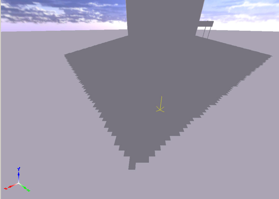
Shadow with 2×2 PCF without linear interpolation:
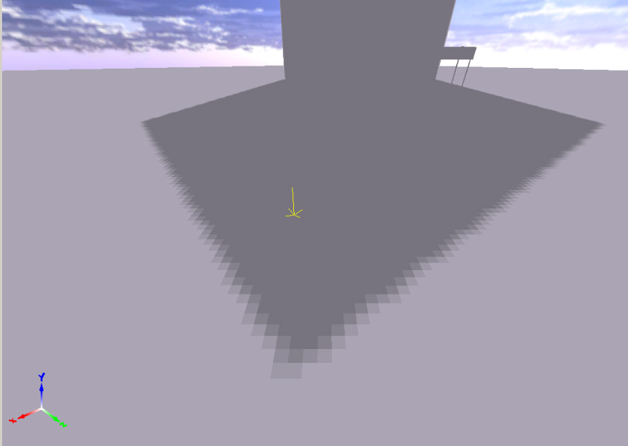
To improve this further, NVIDIA hardware also performs linear interpolation of the resulting values based on the exact position of the screen pixel within shadow-map space. The algorithm is quite simple. The post-perspective XY coordinates of the current pixel in shadow-map space lie within the range [0..1]. By multiplying them by the shadow-map resolution, the integer part of the result gives us the coordinates of the shadow-map texel corresponding to the current screen pixel. The fractional part, on the other hand, gives us the sub-texel position of the pixel within that shadow-map texel.
Illustration:
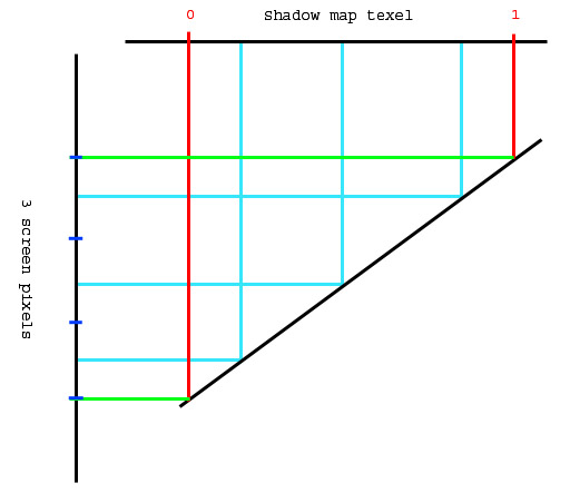
This image shows a mapping where a single shadow texel corresponds to three screen pixels. This is exactly the infamous perspective aliasing problem that all perspective shadow-map techniques (PSM, TSM, LiSPSM, and others) attempt to solve to varying degrees. But that's not what we're discussing right now. In our example, all three screen pixels have the same integer coordinates in shadow-map space. However, the fractional part differs. That fractional component provides the sub-pixel precision that allows us to further smooth the edges of shadowed regions. For the top screen pixel it is approximately 0.8. For the middle one, 0.5. For the bottom one, 0.2.
Now let's look at the view from the shadow map's perspective (an enlarged 2×2 region):
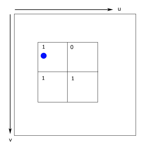
The blue circle indicates the sub-texel position of the screen pixel within the shadow map. The numbers represent the results of comparing the depth stored in the shadow map with the depth of the screen pixel being tested:
1 = in shadow
0 = lit
Let's take the upper two texels of the shadow map. With a straightforward approach (ignoring the sub-texel position), the resulting shadow intensity would be:
(1 + 0) / 2 = 0.5
However, we know that in our example the pixel's sub-texel position along the U axis is approximately 0.2. Therefore, instead of simply averaging neighboring values, we can linearly interpolate between them according to the sub-texel position. Thus, the shadow intensity becomes:
x + s(y - x)

= 1 + 0.2(0 - 1)

= 0.8
As we continue moving along the U axis, the resulting shadow intensity gradually decreases. This produces a smooth shadow gradient. The same procedure is applied along the V axis. This is exactly how NVIDIA engineers implemented the algorithm in hardware.
The result speaks for itself:

Shader code fragment used to emulate NVIDIA hardware behavior on ATI cards:
// Perform Percentage Closer Filtering
// First determine lerp amounts
float4 la;
float2 texLA = frac(fragPos.xy * shadowMapSize.xy);

// Gather samples
// Fetch 4 neighbour points
depth.x = tex2D(shadow_s, fragPos).r;
depth.y = tex2D(shadow_s, fragPos + float4(shadowMapSize.z, 0.0, 0.0, 0.0)).r;
depth.z = tex2D(shadow_s, fragPos + float4(0.0, shadowMapSize.w, 0.0, 0.0)).r;
depth.w = tex2D(shadow_s, fragPos + float4(shadowMapSize.z, shadowMapSize.w, 0.0, 0.0)).r;

// Check visibility for all points
depth = depth < fragPos.zzzz ? 0.0 : 1.0;

// Final shadow factor
return lerp
(
    lerp(depth.x, depth.y, texLA.x),
    lerp(depth.z, depth.w, texLA.x),
    texLA.y
);
Questions?